| Issue |
Security and Safety
Volume 4, 2025
Security and Safety for Next Generation Industrial Systems
|
|
|---|---|---|
| Article Number | 2025008 | |
| Number of page(s) | 21 | |
| Section | Industrial Control | |
| DOI | https://doi.org/10.1051/sands/2025008 | |
| Published online | 26 October 2025 | |
Research Article
Vulnerability assessment of high-voltage direct current transmission systems to cyberattacks
1
State Key Laboratory of Industrial Control Technology and College of Control Science and Engineering, Zhejiang University, Hangzhou 310027, China
2
School of Electrical and Electronic Engineering, University of Sheffield, Sheffield S10 2TN, United Kingdom
* Corresponding authors (email: This email address is being protected from spambots. You need JavaScript enabled to view it.
)
Received:
10
April
2025
Revised:
9
July
2025
Accepted:
9
July
2025
Abstract
High-voltage direct current (HVDC) transmission systems demonstrate significant advantages in long-distance and high-capacity power transmission. Voltage-source converter-based HVDC (VSC-HVDC), with its flexible power flow control and independent active/reactive power regulation capabilities, has been increasingly adopted in large-scale transmission projects. However, the stable operation of HVDC systems relies heavily on reliable communication and control systems, making their cybersecurity vulnerabilities a critical concern. This study focuses on the cyberattacks targeting two-terminal VSC-HVDC systems. We systematically analyze the control architecture and identify vulnerable attack points, and then conduct experimental attacks including denial-of-service (DoS), time-delay, false data injection (FDI), and hybrid attacks, targeting these vulnerable nodes. To enhance the experimental authenticity, the real-time simulation experiments were performed on the OPAL-RT OP5707 XG platform. The experiments involved both individual and simultaneous cyberattacks on the two converter stations, yielding a series of attack-induced effects. The results demonstrate that cyberattacks can induce severe consequences including DC over-voltage, power transmission failure, and system oscillations, all of which pose substantial threats to grid security and stable operation. These findings highlight the urgent need for further cybersecurity enhancement in HVDC control systems.
Key words: Cyberattack / High-voltage direct current / Voltage-source converter / Vulnerability assessment
Citation: Guo R, Liu M and Deng R. Vulnerability assessment of high-voltage direct current transmission systems to cyberattacks. Security and Safety 2025; 4: 2025008. https://doi.org/10.1051/sands/2025008
© The Author(s) 2025. Published by EDP Sciences and China Science Publishing & Media Ltd.
 This is an Open Access article distributed under the terms of the Creative Commons Attribution License (https://creativecommons.org/licenses/by/4.0), which permits unrestricted use, distribution, and reproduction in any medium, provided the original work is properly cited.
1. Introduction
The proportion of renewable energy in global electricity generation continues to increase, with projections indicating that over 50% of electricity will come from renewable sources by 2040 [1]. However, large-scale renewable power plants are typically located far away from load centers [2], significantly increasing the demand for efficient long-distance power transmission, particularly for offshore wind farms where AC cables over 50 km suffer from significant capacitive charging currents that substantially reduce effective transmission capacity [3]. Under these conditions, high-voltage direct current (HVDC) transmission systems demonstrate clear advantages over high-voltage alternating current (HVAC) transmission. The most notable feature of HVDC is its low losses over long distances [4]. The broader applications of HVDC in power systems are also reflected in several aspects: (1) Facilitating large grid interconnections to improve power supply reliability and economic operation efficiency while avoiding issues like increased short-circuit capacity and expanded fault ranges inherent in HVAC; (2) Promoting electricity market operations, as HVDC enables flexible power flow control unaffected by operational conditions at either AC grid terminal, preventing loop flows or circulating currents that challenge HVAC; (3) Supporting renewable energy integration, where the suitability of HVDC for large-scale long-distance and submarine cable transmission provides significant advantages for connecting hydro, solar, onshore and offshore wind power to grids.
HVDC transmission systems can be categorized into three main types based on converter technologies: line-commutated converter (LCC), voltage-source converter (VSC), and modular multilevel converter (MMC). LCC-HVDC employs semi-controlled thyristor-based switching devices that operate according to AC transmission line parameters. Therefore, LCC-HVDC has the following inevitable drawbacks: (1) It requires the AC system to provide commutation current during the switching process, making it susceptible to commutation failure [5]; (2) It is incapable of supplying power to passive networks; (3) It employs semi-controlled devices, which fundamentally limit its control flexibility to active power regulation while precluding independent reactive power control. With advancements in fully controllable power electronic devices, IGBT-based VSC-HVDC systems have been developed, significantly expanding the application scope of HVDC technology through capabilities unattainable by conventional LCC-HVDC [4]. VSC-HVDC offers several distinct advantages: (1) It is particularly suitable for interconnecting large-scale renewable energy generation with power grids, as it enables independent control of both active and reactive power, thereby improving voltage quality [6] and providing reactive power support [7] while meeting grid code requirements for transient performance; (2) It eliminates the risk of commutation failure, thereby mitigating potential large-scale grid disturbances caused by AC system faults; (3) Its ability to connect passive networks makes it ideal for powering isolated systems such as offshore platforms or island grids [8].
The control and communication systems constitute a critical component within HVDC systems, ensuring their stable and efficient operation while safeguarding key equipment such as converters. HVDC systems typically employ a hierarchical control architecture to achieve multi-level regulation [9]: the highest-level system-wide control provides operational command inputs for each converter station within the network, whereas valve-level control represents the most fundamental control tier, responsible for triggering individual valves that comprise the converters [10]. The communication system facilitates timely transmission of control commands and real-time monitoring of operational status. Typically, optical fiber communication is adopted for high-speed data exchange between equipment within HVDC stations, while power line carrier communication (PLCC) is implemented for data transmission between converter stations and remote dispatch centers [11, 12]. However, HVDC systems demonstrate significantly increased vulnerability to cyberattacks due to their unique operational characteristics, including longer transmission distances, greater quantities of data samples required for wide-area monitoring, control, and protection applications, most critically, their dependence on high-availability communication systems [13]. Cyberattacks targeting HVDC systems may trigger converter station failures, damage critical power electronics devices such as IGBT modules and thyristor valves, and interrupt DC transmission. The control system of LCC-HVDC typically regulates DC currents and DC voltages, with relatively fixed power flow direction. In contrast, the VSC-HVDC can regulate DC voltages, active/reactive powers, offering more degrees of freedom in control and thus higher system flexibility. This makes it easier to achieve the power flow reversal under control. Therefore, cyberattacks targeting VSC-HVDC control systems are more likely to induce diverse attack impacts and therefore satisfy adversaries’ objectives, directly affecting the power transmission of the HVDC system. Consequently, the research on cybersecurity threats to VSC-HVDC systems is urgent and essential for ensuring power system security. To this end, this study focuses on the cyberattacks targeting two-terminal VSC-HVDC systems. We systematically analyze the control architecture and identify vulnerable attack points, and then conduct experimental attacks including denial-of-service (DoS), time-delay, false data injection (FDI), and hybrid attacks, targeting these vulnerable nodes. To enhance the experimental authenticity, the real-time simulation experiments were performed on the OPAL-RT OP5707 XG platform. The experiments involved both individual and simultaneous cyberattacks on the two converter stations, yielding a series of attack-induced effects. The results demonstrate that cyberattacks can induce severe consequences, including DC over-voltage, power transmission failure, and system oscillations, all of which pose substantial threats to grid security and stable operation. These findings highlight the urgent need for further cybersecurity enhancement in HVDC control systems. In particular, the main contributions of this paper are summarized as follows:
-
(1)
Through systematic analysis of HVDC control architectures, the vulnerable components prone to cyberattacks were identified, along with four primary attack types;
-
(2)
Real-time simulation experiments, including DoS, time-delay, FDI, and hybrid attacks, were conducted on the OPAL-RT OP5707 XG platform to validate the consequences of these attacks;
-
(3)
Root-cause analysis was conducted on the post-attack consequences, followed by the identification of critical research questions requiring further investigation.
In subsequent sections, the paper is organized as follows: Section 2 reviews prior work related to this research. Section 3 introduces the hierarchical control architecture of a two-terminal VSC-HVDC system and elaborates on the feedforward decoupling control strategy for its inner-loop current. Section 4 analyzes the vulnerable nodes in the HVDC system and presents four types of cyberattacks along with their mathematical models. Section 5 details the experimental setup, including the test platform and the parameters of the VSC-HVDC system under study, followed by the execution of four cyberattack scenarios and the corresponding experimental results. Section 6 discusses the underlying causes of the attack impacts and outlines potential future research directions. Finally, Section 7 concludes the paper by summarizing the key contributions and findings of this work.
2. Related works
Existing research on HVDC cybersecurity has identified four predominant cyberattack categories: DoS, time-delay, FDI, and replay attacks, with FDI attacks constituting the primary focus of most scholarly investigations [14–17]. These attack vectors enable malicious entities to deliberately compromise system stability, induce substantial frequency deviations and power oscillations, ultimately culminating in either significant degradation of power transmission quality or catastrophic grid-wide blackouts.
The stable operation of HVDC systems, particularly multi-terminal VSC-HVDC, relies on coordinated control centers that send power or voltage commands to converter stations, which then operate stably through multi-level control implementations. As demonstrated by Sahoo et al. [18], FDI attacks targeting various reference values in control strategies can alter controller behavior, disrupt system synchronization, and ultimately lead to system instability or increased power costs with reduced economic efficiency. Ding et al. [19] demonstrated that attackers can manipulate either reference values or measured quantities in MMC controllers, quantitatively assessing the small-signal stability margins of MMC-HVDC control systems under cyberattacks. HVDC systems depend on multiple sensors measuring DC voltage, active and reactive power, where attackers may compromise communication links or directly falsify sensor measurements to inject erroneous data. Qiu et al. [20] revealed the vulnerability of phasor measurement units (PMUs) in HVDC systems to FDI attacks, threatening auxiliary control systems and stability, while proposing a hybrid data-driven control strategy as countermeasure. Chen et al. [21] showed that voltage magnitude and phase angle critically influence the stability of system current and power transmission, while proposing a rule-based cyberattack detection methodology. Devnath et al. [22] evaluated the consequences of FDI attacks on various control units within MMC-HVDC systems, systematically analyzing system vulnerabilities through the analysis of voltage, current and Phase-Locked Loop (PLL) control characteristics. Gholami et al. [23] illustrated that the modified voltage of the HVDC controller may adversely affect power system stability under certain operating conditions, and proposes an enhanced cyberattack strategy that significantly increases switching losses in HVDC systems while degrading overall operational efficiency. Jiang et al. [24] revealed that when FDI attacks occur on the rectifier side of an LCC-HVDC system, it could constrain power transmission capacity, escalate reactive power demand, and ultimately lead to system instability. Hou et al. [25, 26] investigated how subtle FDI attacks on measurement data can trigger heterogeneous equilibrium points in LCC-HVDC and VSC-HVDC systems, causing over-current and power reversal conditions. Liu et al. [27, 28] proposed the idea of proactive detection is introduced into the converter-based microgrids by proactively perturbing the converter control gains, acting as an effective scheme in revealing stealthy FDI attacks with trivial impact on the normal system operation.
The aforementioned research primarily focuses on FDI attacks. Additionally, some scholars have conducted investigations into DoS, time-delay, and replay attacks. DoS attacks can disrupt signal transmission, thereby preventing the control system from accurately assessing the current operational state of the system and consequently impairing its ability to execute appropriate control actions. Sahoo et al. [18] demonstrated that a DoS attack targeting parameter ω in the secondary controller of a VSC-HVDC system can disrupt the synchronization mechanism among voltage source converters, potentially leading to system instability. Pan et al. [29] utilized a system-theoretic approach to investigate the impacts of DoS attacks on load frequency control (LFC) models in power systems, conducting comparative analysis between systems with and without HVDC links as well as those incorporating emulated inertia. Liu et al. [30] proposed a Markov-based stochastic stabilization control scheme for MMC-HVDC systems, where time-delay components are compensated via a second-order communication disturbance observer (CDO), while effectively mitigating DoS attacks impact without requiring complete knowledge of the attack state information. Time-delay attacks intentionally delay signal transmission to the controller, causing control actions to lag behind the actual system state. Replay attacks retransmit historical operational data from a specific time period to the controller. These deceptive operations prevent the control system from obtaining accurate real-time system states, which may result in control errors and ultimately jeopardize system stability. Fan et al. [31] presented the first systematic investigation of cyberattack impacts on HVDC transmission oscillation damping control, demonstrating that replay attacks and time-delay attacks can induce severe oscillations and even instability in AC-HVDC systems. Roy et al. [32] proposed a multi-agent-based security framework for HVDC systems, which demonstrates superior attack detection performance against time-delay, data interruption, and replay attacks compared to conventional learning-based approaches such as SVM, KNN, and Adaboost. Zhang et al. [33] proposed an intrusion detection scheme for DC line protection in multi-terminal HVDC systems, consisting of a passive phase followed by an active phase. Experimental results demonstrate that this scheme can detect various cyber attacks, including the most sophisticated and stealthy synchronous replay attacks.
Nevertheless, there is still a lack of a comprehensive vulnerability assessment of the HVDC control system to cyberattacks, which is crucial for raising the security awareness from related stakeholders and providing guidelines on designing detection and response strategies. To fill the research gap, this paper aims to conduct this security analysis study for HVDC control systems considering the single cyberattack such as DoS, time-delay, and FDI attacks, as well as the hybrid one. Based on extensive experimental results from the real-time HVDC control system testbed, the essential principles between malicious link block/data modification and hazardous physical impacts are thoroughly analyzed, aiming to attract attention from IT security and control engineering to facilitate the cybersecurity enhancement of HVDC control systems.
3. Hierarchical control framework of VSC-HVDC
In a two-terminal VSC-HVDC system, the outer-loop control objectives typically include active power P [34], reactive power Q [35], and DC voltage Udc [36]. The dispatching center sends reference values of P, Q, and Udc to the converter stations at both ends of the HVDC system according to the power transmission requirements. The outer-loop control of each converter station receives the reference values from the dispatching center and the measured values from its own measurement system. Through the outer PI controller, the reference current for the inner loop is generated. The controller of the inner current loop outputs a voltage regulation signal. The adjustment of voltage modifies the current through the grid AC-side dynamics, thereby achieving closed-loop control of the inner current loop. Specifically, the voltage output by the inner-loop controller undergoes further calculations to generate the Pulse-Width Modulation (PWM) signal Umod, which is then compared with the triangular carrier signal to generate trigger signals for controlling the on/off of IGBTs. Thereby achieving the objective of adjusting the active/reactive power and DC voltage of the HVDC system. As shown in Figure 1, it is a two-terminal VSC-HVDC system with a hierarchical control architecture [37]. The rectifier-side controls active/reactive power, while the inverter-side regulates DC voltage and reactive power. In the dq rotating coordinate system, the active power and reactive power of the converter are respectively:
 (1)
(1)
 (2)
(2)
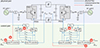 |
Figure 1. The hierarchical control of two-terminal VSC-HVDC |
where Usd and isd respectively represent the d-axis components of voltage and current on the grid AC side, and equivalently, Usq and isq respectively represent the q-axis components of voltage and current on the grid AC side. Since the d-axis of the d-q rotating coordinate system is aligned with the grid voltage vector under the PLL control, Usq = 0 and the magnitude of Usd is equal to the modulus of the grid voltage vector [38]. Therefore, the aforementioned formula can be simplified as:
 (3)
(3)
 (4)
(4)
In an actual infinite AC system, the variation in the magnitude of the grid voltage vector can be neglected and approximated as a constant. Thus, the active power and reactive power can be independently controlled by isd and isq respectively, increasing the control system freedom simultaneously. The constant DC voltage control is mainly used to maintain the stability of the grid DC side voltage of the HVDC system, which also helps to balance the active power of the system.
The outer-loop control system receives reference values from the dispatching center and measurement feedback from sensor circuits. Malicious manipulation of either component can directly compromise the output of the outer-loop PI controller, subsequently distorting the inner-loop current regulation and ultimately leading to system instability or operational failures.
3.1. Phase-locked loop control
The three-phase AC voltages and currents are transformed into the dq coordinate system rotating synchronously with the grid voltage through the Park’s transformation [39]. As shown in Figure 2a, in the three-phase system, the sum of the three-phase voltage vectors  can be expressed as:
 (5)
(5)
 |
Figure 2. The voltage vector and PLL control: (a) voltage vector in d-q frame; (b) diagram of PLL |
where ω0 and θ0 represent the angular frequency and the initial phase angle respectively in the stationary α-β coordinate system, respectively. Then, the phase of the grid voltage is tracked via a phase-locked loop (PLL) control scheme. Assuming that the locked phase angle is ρ, then in the coordinate system, there is:
 (6)
(6)
where Uδd and Uδq represent the projections of  onto the d-axis and q-axis respectively. When Uδq = 0, i.e., the locked phase angle ρ is infinitely close to ω0
t + θ0, then ω0
t + θ0 − ρ ≈ 0, there is:
onto the d-axis and q-axis respectively. When Uδq = 0, i.e., the locked phase angle ρ is infinitely close to ω0
t + θ0, then ω0
t + θ0 − ρ ≈ 0, there is:
 (7)
(7)
Achieving the tracking of ρ through closed-loop control is a prerequisite for Park’s transformation, which provides an accurate and reliable transformation calculation angle for abc-dq and dq-abc transformations. Therefore, the PLL control loop, as shown in Figure 2b, is established according to Equation (7) [40]. Set ρref = ω0 t + θ0, when ρ > ω0 t + θ0, Uδq < 0, so the value of ω decreases. When ρ < ω0 t + θ0, Uδq > 0, so the value of ω increases. It is seen that the PLL control loop adjusts the output frequency ω by using Uδq as the input of the compensator. When ω = ω0, the output frequency reaches a stable value, and then it is sent to the abc-dq and dq-abc transformation of the control system of HVDC.
In Figure 1, the abc-dq transformation in converter station 1 receives the three-phase voltage Usabc1 and three-phase current Isabc1 measured by sensors, as well as the phase-locked angle ρ1 from the PLL. After calculation by the transformation, it outputs Usd1, Usq1, Isd1, and Isq1 in the dq coordinate system. The dq-abc transformation receives the modulation signals Umodd1 and Umodq1 in the dq coordinate system outputted by the controller, transforms them into Umodabc1 in the abc three-phase coordinate system, and then uses them to generate the trigger signals for the IGBTs. Similarly, the abc-dq and dq-abc transformations in converter station 2 follow the same principle.
The locked phase angle ρ critically determines the synchronization accuracy of the dq rotating reference frame. If compromised, this angle would distort the d- and q-axis components of both voltage and current, leading to erroneous control loop outputs that may severely threaten system stability. Attackers can achieve their objectives by deliberately manipulating the PLL’s output phase angle ρ, thereby corrupting the phase reference for dq-frame control.
3.2. Inner current control
Figure 3 shows the three-phase VSC operating in inverter mode, where L represents the line inductance on the grid AC side, Requiv represents the equivalent resistance between the converter and the grid AC side, Uv represents the output voltage of the converter, Us and is respectively represent the voltage and current on the grid AC side. Based on Kirchhoff’s voltage law, each phase in the three-phase AC circuit exhibits the following relationship:
 (8)
(8)
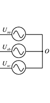 |
Figure 3. The AC-side equivalent circuit of three-phase VSC inverter |
To facilitate controller design, Equation (8) is converted to the dq synchronous frame via Park’s transformation, yielding:
 (9)
(9)
 (10)
(10)
where Uvd and Uvq represent the projections of Uv onto the d-axis and q-axis respectively, Usd and Usq represent the projections of Us onto the d-axis and q-axis respectively,  , and under the control of the PLL, ω(t)=ω0. It can be seen that isd and isq are not only affected by Uvd and Uvq, but also influenced by the current cross-coupling terms Lω(t)isq and Lω(t)isd, as well as the disturbances from voltages of the grid AC side Usd and Usq.
As shown in Figure 4, the inner-loop reference current commands of both the rectifier-side and the inverter-side are determined by their respective outer-loop control loops. In the inner current loop control, a voltage coupling compensation term is introduced to perform decoupling control on the current. Meanwhile, by implementing feed-forward compensation for the grid voltage, not only the independent decoupling control of the d-axis and q-axis currents achieved, but also the dynamic performance of the system is improved. It is worth noting that, while is represents the inner-loop control variable and Uv denotes the manipulated variable, the voltage output from the inner loop assumes the role of the actual control variable when employed for PWM signal synthesis. The corresponding implementation equation is:
![Mathematical equation: $$ \begin{aligned}&U_{vd}=U_{sd}-L\omega _0i_{sq}+\left[k_{p1}\left(i_{sdref}-i_{sd}\right) +k_{i1}\int \left(i_{sdref}-i_{sd}\right)\mathrm{d}t\right], \end{aligned} $$](/articles/sands/full_html/2025/01/sands20250011/sands20250011-eq14.gif) (11)
(11)
![Mathematical equation: $$ \begin{aligned}&U_{vq}=U_{sq}+L\omega _0i_{sd}+\left[k_{p2}\left(i_{sqref}-i_{sq}\right) +k_{i2}\int \left(i_{sqref}-i_{sq}\right)\mathrm{d}t\right]. \end{aligned} $$](/articles/sands/full_html/2025/01/sands20250011/sands20250011-eq15.gif) (12)
(12)
 |
Figure 4. The inner current control loop for VSC-HVDC |
4. Attack models in HVDC control systems
4.1. Emerging cyber vulnerabilities
The cyberattacks on the HVDC system originate from its highly dependent communication and control systems, which can be fundamentally categorized into three primary dimensions: (1) There are security flaws in the Supervisory Control and Data Acquisition (SCADA) communication protocols of the HVDC system [41]. Industrial communication protocols such as IEC 61850, DNP3, and Modbus are widely adopted in the HVDC system [42]. However, when these protocols were initially designed, network security was not fully considered, making them vulnerable to threats such as Man-in-the-Middle (MITM), DoS, and data tampering attacks [43]. For example, exploiting vulnerabilities in the Modbus protocol, attackers can send unauthorized read/write commands to tamper with device operation instructions, causing the equipment to deviate from its normal operating state. (2) Modern HVDC systems usually employ software-based control systems, which typically run on platforms like Windows or Linux, this expands the exposure surface of the control system to conventional IT cyber vulnerabilities. Attackers typically tamper with the source code of platform-related software or conduct supply-chain attacks by poisoning software dependencies [44]. In addition, remote monitoring and maintenance interfaces may also serve as entry points for attacks on the control system. MITM, DoS, and code injection attacks are among the prevalent attack vectors directed at such vulnerabilities. (3) The coordination between converter stations in HVDC systems and the hierarchical control within individual converter stations are fundamentally dependent on high-precision time synchronization. Attackers can carry out GPS spoofing [45], causing the system to lose synchronization and thus affecting control stability.
The accurate regulation of HVDC control systems fundamentally depends on measured grid voltages and currents as critical feedback signals for control loops. However, these systems face dual security threats: First, adversaries can manipulate measurement data through communication channel attacks. More significantly, current and voltage sensors represent vulnerable entry points for attacks. Particularly concerning are sensor-targeted attacks via electromagnetic interference (EMI), which can bypass conventional network security defenses like anomaly traffic detection. Malicious actors can deploy concealed EMI devices near sensors and remotely inject precisely calibrated interference signals with specific frequencies and amplitudes. These electromagnetic fields couple into sensor circuits, where operational amplifiers unintentionally rectify and amplify the adversarial signals [46]. This sophisticated attack vector ultimately enables adversaries to achieve their objectives while evading traditional cyber security mechanisms.
4.2. Attack models
The HVDC control system ensures stable operation according to specified commands, making both the control system and its communication network prime targets for cyberattacks. Attackers can induce system malfunctions by injecting false control commands or tampering with measurement data. Furthermore, by exploiting vulnerabilities in the communication network to launch DoS or time-delay attacks that disrupt normal communications, attackers alter the input signals to the control system. This subsequently modifies the output trigger pulse signals of the controller, causing the converter valves to deviate from their normal operating state and potentially resulting in valve damage.
The PLL continuously monitors the phase and frequency of the AC grid in real-time, providing synchronous reference signals for converter operation, making it a core component of HVDC control systems. Attackers can manipulate PLL input signals to distort phase-angle tracking, directly falsifying phase-angle data, or introducing time-delays in phase synchronization [47]. These malicious interventions may lead to control failure and operational fault.
In this work, cyberattacks are launched on the control system measurement data and the phase-locked angle signal output from the PLL. The regulation of active power and DC voltage constitutes the primary control objectives in this HVDC system. At the grid AC side of converter station 1, the control part receives active power measurement data, and a DoS attack is implemented on this measurement signal as follows:
 (13)
(13)
where ta represents the start time of the attack, Δt denotes the attack duration, P1a represents the active power measurement value transmitted to the outer-loop controller of converter station 1, and P1meas represents the actual active power measured by the sensor. Similarly, at the grid AC side of converter station 2, the control part receives DC voltage measurement data, where the DoS attack can be expressed as:
 (14)
(14)
where Udc2a represents the DC voltage measurement value transmitted to the outer-loop controller of converter station 2, and Udc2meas represents the actual DC voltage measured by the sensor.
When a time-delay attack is applied to the phase angle of the PLL output signal. The attack expressions for converter stations 1 and 2 are identical, as specified below:
 (15)
(15)
where ρa represents the phase-locked angle data transmitted to the subsequent calculation block, ρmeas represents the phase-locked angle output from the PLL, and τ represents time-delay value of attack.
FDI attacks target the measurement data of the HVDC system in converter stations, and thus for converter station 1, the following impacts:
 (16)
(16)
where a1 represents the attack injection value of active power. Similarly, for converter station 2, the same formulation applies:
 (17)
(17)
where a2 represents the attack injection value of DC voltage. In this work, both attack injection values a1 and a2 are normalized in per-unit (pu) system according to control system characteristics.
A DoS attack prevents measurement signals from being transmitted normally to the control system, while an FDI attack injects false data into the system, leading to incorrect decisions. Combining these two into a hybrid attack may enhance the attack impact. In this work, we will also conduct hybrid attacks combining FDI attacks on control commands or measurement data with DoS attacks on measurement signals. In the hybrid attack, both attacks may simultaneously target the same converter station or separately attack two different converter stations at the same time.
5. Experimental case studies
5.1. Real-time simulation testbed
To more realistically simulate the behavior of the HVDC system under cyberattacks, an experimental platform based on the OPAL-RT simulator OP5707 XG was established for real-time simulation, and attack experiments were conducted on this platform. As shown in Figure 5, the simulation model was built in MATLAB, which includes the SM_computation block and the SC_GUI block. The SM_computation module contains the physical HVDC system and its control system, while the SC_GUI module contains real-time measurements. The RT-LAB software serves as the interface between MATLAB and the real-time OPAL-RT simulator, loading the model onto the real-time target and, in turn, acquiring real-time data.During actual operation, the SM_computation module in MATLAB is deployed to the real-time target for real-time computation, while the SC_GUI module runs on the host PC to display real-time measurements. Communication between the host PC and the real-time target is achieved via TCP/IP. Asynchronous communication is employed between the Host PC and the Real-time target, whereas synchronous communication is utilized within the Real-time target. In real-time attack experiments, attacks are deployed within the SM_computation module and launched against the control system, which could potentially penetrate the host control unit to alter the actual controller. The key physical parameters of the HVDC system are specified in Table 1, with the DC transmission line parameters sourced from Reference [48].
 |
Figure 5. The testbed by using OPAL-RT |
The parameters of two-terminal VSC-HVDC
5.2. Denial-of-service attack
As shown in Figure 6, at t = 3 s, a DoS attack is launched on the active power measurement of converter station 1, because of the inherent minor fluctuation of HVDC system, the active power output of converter station 1 gradually deviates from its normal value and continues to increase, while the absorbed active power at converter station 2 correspondingly rises, and the DC voltage remains stably maintained at its rated value under the control of converter station 2. Subsequently, at t = 6 s, another DoS attack is executed on the DC voltage measurement of converter station 2, the DC voltages at both converter station 1 and converter station 2 rise simultaneously and fail to re-stabilize. Finally, at t = 9 s, the attacks on both terminals are stopped at the same time, both the active power and DC voltage can return to their normal values within a short period.
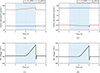 |
Figure 6. The output of HVDC system under DoS attack: (a)-(b) active and reactive power of converter stations 1 and 2; (c)-(d) DC voltages of converter stations 1 and 2. The blue shaded regions indicate the attack periods |
5.3. Time-delay attack
As shown in Figure 7, at t = 2 s, a time-delay attack is launched on the PLL output signal ρ1 of converter station 1, with a delay time of 0.05 s, and it can be observed that the active power output of converter station 1 exceeds 500 MW, while its reactive power shifts from consumption to generation, concurrently, the absorbed active power at converter station 2 exhibits a slight increase. Both terminal DC voltages of the HVDC system experience rapid escalation beyond 600 kV, which significantly increases line losses and may potentially lead to equipment damage or converter valve failures. The attack on converter station 1 is removed at t = 4 s; at t = 6 s, a time-delay attack is executed on the PLL output signal ρ2 of converter station 2, with the same delay time of 0.05 s, then, the DC voltages at converter stations 1 and 2 experience a sharp rise beyond the normal operating range. At the same time, converter station 2 transitions from absorbing active power to injecting power into the system to compensate for the increased power consumption caused by the DC voltage elevation, while simultaneously exhibiting a reversal in its reactive power flow direction. However, converter station 1 maintain its original active and reactive power operation through controlled regulation. When the attack is removed at t = 8 s, the DC voltage, active power, and reactive power have all returned to their rated values.
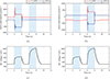 |
Figure 7. The output of HVDC system under time-delay attack in case 1: (a)-(b) active and reactive power of converter stations 1 and 2; (c)-(d) DC voltages of converter stations 1 and 2. The blue shaded regions indicate the attack periods |
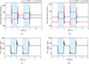 |
Figure 8. The output of HVDC system under time-delay attack in case 2: (a)-(b) active and reactive power of converter stations 1 and 2; (c)-(d) DC voltages of converter stations 1 and 2. The blue shaded regions indicate the attack periods |
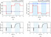 |
Figure 9. The output of HVDC system under FDI attack in case 1: (a)-(b) active and reactive power of converter stations 1 and 2; (c)-(d) DC voltages of converter stations 1 and 2. The blue shaded regions indicate the attack periods |
As shown in Figure 8, at t = 2 s, a time-delay attack is launched only on the phase-locked angle of the dq to abc transformation calculation block in the control signal channel of converter station 1, with a time delay of 0.05 s, the active power transfer at both converter station 1 (sending end) and converter station 2 (receiving end) decays synchronously to negligible levels, while the DC voltage drops from its rated value to zero levels, resulting in the complete interruption of normal active power transmission. Meanwhile, the reactive power at both terminals increases and is injected into the system. This attack is removed at t = 4 s; at t = 6 s, a delay attack is executed only on the phase-locked angle of the dq to abc calculation in the control signal channel of converter station 2, with the same time delay of 0.05 s, the behavior of the HVDC system exhibits fundamental consistency with the time-delay attack on converter station 1, transitioning into a zero active power transmission state. The attack is removed at t = 8 s.
5.4. False data injection attack
As shown in Figure 9, at t = 2 s, an FDI attack is launched by injecting an attack value of 0.9 pu into the active power measurement data of converter station 1. The active power output of converter station 1 experiences a significant reduction, while converter station 2 undergoes a power flow reversal, transitioning to active power injection into the system. Through DC voltage control actions, the DC voltages at both terminals are rapidly regulated and successfully maintained at their rated values despite these power change disturbances, and the attack is removed at t = 5 s; at t = 7 s, another FDI attack is executed by injecting an attack value of −0.2 pu into the active power measurement data of converter station 1. The active power output of converter station 1 increases by 60 MW, while the absorbed active power at converter station 2 increases by 42 MW. Simultaneously, the DC voltage increases by over 40 kV, leading to increased active power consumption in the system. The attack is removed at t = 10 s. Despite transient fluctuations in reactive power at both terminals caused by these active power variations, the reactive power remains stabilized at its rated value. This observation clearly demonstrates the decoupled control capability between active and reactive power in the VSC-HVDC system.
As shown in Figure 10, at t = 2 s, an FDI attack is launched by injecting an attack value of 0.25 pu into the DC voltage measurement data of converter station 2, it can be observed that the DC voltage decreases while the active power absorption at converter station 2 increases, exhibiting oscillatory behavior that leads to system instability. Furthermore, the reactive power at converter station 2 also exhibits oscillatory behavior; at t = 4 s, the attack value is increased to 0.5 pu, the amplitudes of oscillations in both the DC voltage and the active power at converter station 2 exhibit further escalation, indicating deteriorating system stability, the attack is removed at t = 6 s; at t = 8 s, an FDI attack is executed by injecting an attack value of −1.5 pu into the DC voltage measurement data of converter station 2, the DC voltages at both terminals of the HVDC system rise to approximately 750 kV, while converter station 2 experiences a reversal in active power flow direction to compensate for increased system demand. The attack is removed at t = 10 s, during the FDI attack targeting converter station 2, converter station 1 maintains both active and reactive power at their rated values without any transient oscillation.
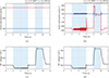 |
Figure 10. The output of HVDC system under FDI attack in case 2: (a)-(b) active and reactive power of converter stations 1 and 2; (c)-(d) DC voltages of converter stations 1 and 2. The blue shaded regions indicate the attack periods |
The FDI attack injection values described above have specific amplitudes. For time-varying attacks such as gradually increasing FDI strength, the implementation is shown in Figure 11. At t = 2 s, false data with time-varying amplitude is injected into the active power measurement data of converter station 1, increasing uniformly at a rate of 0.1 pu per second. After three seconds, the attack amplitude reaches 0.3 pu. During this process, the active power output by converter station 1 and the active power absorbed by converter station 2 both decrease uniformly. Additionally, by amplifying the DC voltage output curve at t = 2 s, it can be observed that the DC voltage decreases by a small amount of approximately 0.4 kV. The attack is removed at t = 5 s. Subsequently, at t = 7 s, false data is injected into the DC voltage measurement data of converter station 2, increasing uniformly at 0.1 pu per second and reaching 0.3 pu at t = 10 s. During this process, the DC voltages at both ends decrease uniformly, and the active power absorbed by converter station 2 increases uniformly. When the DC voltage drops to approximately 225 kV, it stops decreasing and starts to oscillate. At the same time, the active power absorbed by converter station 2 also ceases to rise and simultaneously begins to oscillate. The attack is removed at t = 10 s, after which the system resumes normal operation.
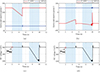 |
Figure 11. The output of HVDC system under FDI attack in case 3: (a)-(b) active and reactive power of converter stations 1 and 2; (c)-(d) DC voltages of converter stations 1 and 2. The blue shaded regions indicate the attack periods |
5.5. Hybrid attack
As shown in Figure 12, at t = 2 s, a hybrid attack combining a DoS attack on measurement signals and an FDI attack with −0.1 pu on control command is launched on the active power of converter station 1, the output active power of converter station 1 decreases rapidly, leading to a reversal in power flow direction. Ultimately, converter station 1 transitions to absorb active power from the system, with both its active and reactive power exhibiting sustained oscillations. Concurrently, converter station 2 also experiences a power flow reversal, shifting from active power absorption to injection. The DC voltages at both converter stations drop to approximately 220 kV, accompanied by persistent oscillations. After removing this attack at t = 5 s, a hybrid attack combining a DoS attack on measurement signals and an FDI attack with −0.1 pu on control command is executed on the DC voltage of converter station 2 at t = 8 s. The DC voltage drops to approximately 220 kV with accompanying oscillations. Meanwhile, converter station 2 experiences a slight increase in absorbed active power along with oscillatory behavior in both active and reactive power. In contrast, converter station 1 remains unaffected by the attack, maintaining stable active and reactive power outputs at their rated values. The attack is removed at t = 11 s.
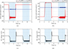 |
Figure 12. The output of HVDC system under hybrid attack in case 1: (a)-(b) active and reactive power of converter stations 1 and 2; (c)-(d) DC voltages of converter stations 1 and 2. The blue shaded regions indicate the attack periods |
As shown in Figure 13, at t = 2 s, a DoS attack is initiated on the active power measurement of converter station 1 while concurrently performing an FDI attack with −0.1 pu on the DC voltage measurement data of converter station 2, the DC voltage rises to approximately 330 kV, while converter station 2 exhibits a slight decrease in active power absorption. Concurrently, converter station 1 demonstrates a gradual, minimal-rate increase in active power output, indicating elevated system power consumption. The attacks on both terminals are simultaneously withdrawn at t = 5 s. Subsequently, at t = 8 s, a DoS attack is implemented on the DC voltage measurement of converter station 2 while simultaneously conducting an FDI attack with −0.1 pu on the active power measurement data of converter station 1. The active power output of converter station 1 increases to approximately 330 MW, while the absorbed active power at converter station 2 gradually decreases. Concurrently, the DC voltage becomes unregulated and exhibits a continuous rise. The attacks are terminated at t = 11 s. During both hybrid attacks, the reactive power remains stably maintained at its rated value.
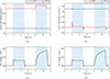 |
Figure 13. The output of HVDC system under hybrid attack in case 2: (a)-(b) active and reactive power of converter stations 1 and 2; (c)-(d) DC voltages of converter stations 1 and 2. The blue shaded regions indicate the attack periods |
6. Discussion
6.1. Attack impact analysis
The HVDC system exhibits sustained oscillations under both FDI and FDI-DoS hybrid attack conditions. In the normal state, the PWM waveform exhibits continuous and regular transitions between 0 and 1. When the attack occurs, transitions halt for 1 to 2 milliseconds approximately every 10 milliseconds. During this period, a corresponding IGBT remains persistently in the conducting or off state, which may serve as the underlying cause of system oscillations. Additionally, the output of the controller oscillated without reaching the amplitude limit. The oscillatory phenomena may trigger severe system instability, potentially resulting in power transmission interruption and accelerated aging of electrical equipment.
Under the time-delay, FDI, and hybrid attack scenarios, converter station 2 exhibits active power flow reversal, accompanied by a significant rise in DC voltage. This demonstrates that system DC voltage elevation leads to increased active power consumption by both AC-side components and the converter stations themselves. Furthermore, hybrid attacks may force active power transmission from converter station 2 to converter station 1, directly contradicting the designated operational objectives of the HVDC system.
During a DoS attack, the inability to transmit measurement data to the controller results in persistent deviations from reference values. When the measured value is marginally below the reference, the controller generates an output that elevates the voltage. Nevertheless, the absence of measurement data feedback to the controller results in continuous actuation and erroneous output. Consequently, the DC voltage and active power output exhibit continuous escalation. When the DC voltage exceeds the maximum allowable threshold, it may lead to equipment overload and potential damage. Notably, if the DoS attack occurs during a different operational phase (when measured values under fluctuations exceed reference values), the DC voltage and active power output may exhibit decline instead.
During a time-delay attack, the system exhibits a complete collapse of both active power and DC voltage at dual converter stations to zero, demonstrates that time-delay can potentially deprive the system of its power transmission capability, forcing it into a shutdown operational state.
The above attack experiments were conducted under a specific set of grid and converter parameters. When these parameters are altered, the impacts of attacks on the HVDC system may vary accordingly: (1) When the attack on converter station 2 causes the DC voltage to rise, the active power consumed by the AC-side grid will increase. However, if the transformer ratio is increased, it is equivalent to increasing the AC-side source voltage. Since the AC-side source voltage is higher than the original value, the magnitude of the increase in active power consumed by the AC-side grid when the DC voltage increases is smaller than before. When the active power of converter station 1 is maintained stable under control, the decrease in the active power absorbed by converter station 2 becomes less significant. Therefore, under the attack of the same magnitude, power reversal may not occur in converter station 2; (2) in FDI and hybrid attacks, whenever the DC voltage drops to approximately 225 kV or even lower, the system will oscillate. This is likely caused by the existence of a voltage lower limit in the system under certain grid and converter parameters. If the line impedance of the grid changes, this voltage lower limit of the system may also change, thereby increasing or decreasing the system’s tolerance to attack amplitudes.
6.2. Future directions
Future directions will establish mathematical expressions describing post-attack dynamics of key parameters like active power and DC voltage based on HVDC system electrical characteristics, enabling precise quantitative assessment of various attack impacts through analytical modeling and simulation validation. While current attacks visibly alter system outputs, we propose developing stealthy attack methods that modify internal states without resulting in detectable output changes. This will be achieved through optimized attack node selection, hybrid attack-type combinations, and carefully calculated attack magnitudes below conventional detection thresholds. Additionally, the detection of cyberattacks can be achieved through the method of Irregular DC Voltage Trends (IDVT). When abnormal fluctuations in DC voltage occur or the voltage slowly drifts beyond the permissible range, and after excluding factors such as changes in its own operating conditions, it can be inferred that a cyberattack has occurred. Furthermore, attacks targeting the phase-locked angle can be detected via PLL drift monitoring to ensure its accuracy. This work has implemented diverse attack scenarios on HVDC system. However, three critical research challenges remain: accurate identification of compromised nodes of HVDC system, real-time detection and quantification of attack characteristics like type and magnitude, and design of adaptive responsive strategies to neutralize attack effects.
7. Conclusion
This paper analyzes the critical applications of HVDC systems in power systems and highlights the advantages of VSC-HVDC systems over traditional DC transmission systems. Modern power systems, undergoing digital transformation, commonly face cybersecurity challenges. Research indicates that HVDC systems are also vulnerable to cyber threats and security challenges. This study provides detailed modeling and analysis of three key components in two-terminal VSC-HVDC systems: phase-locked loop control, inner-loop current control, as well as outer-loop voltage and power control, introducing the feed-forward decoupling control method for inner-loop current. Based on the control architecture, this paper analyzes system components and communication links vulnerable to cyberattacks, followed by modeling of DoS, time-delay, and FDI attacks in HVDC systems. Experiments are conducted on the OPAL-RT real-time simulator OP5707 XG, demonstrating realistic attack effects and providing feasible interfaces for future hardware-in-the-loop implementation. Various attacks are performed on the two-terminal VSC-HVDC system, including DoS, time-delay, FDI, and hybrid attacks, targeting active power measurements and reference values, DC voltage measurements and reference values, and PLL output phase angles. These attacks ultimately cause several consequences in the HVDC system: continuous increase or decrease of active power transmission, reversal or near-zero active power flow direction, continuous rise or drop of DC voltage to zero, and simultaneous oscillations in active power, reactive power, and DC voltage. For the aforementioned attack effects, a theoretical causal analysis is conducted, followed by proposed future research directions.
Acknowledgments
No Acknowledgments.
Funding
This work was supported in part by the National Natural Science Foundation of China under Grant 62293503, 62293500, 62293502, in part by the Natural Science Foundation of Zhejiang Province under Grant LR23F030001, in part by the Frontier Technologies R&D Program of Jiangsu under Grant BF2024065, in part by the State Key Laboratory of Industrial Control Technology under Grant ICT2024A13, ICT2025C04, in part by the Xiaomi Foundation, and in part by the Fundamental Research Funds for the Central Universities 226-2025-00165.
Conflicts of interest
The author declare no conflicts of interest.
Data availability statement
The original data used in this study are available from the corresponding author upon reasonable request.
Author contribution statement
Rong Guo: Primarily responsible for conceptualization, theoretical analysis, and methodology development, as well as investigation design, experimental planning, result visualization, and drafting the original manuscript. Mengxiang Liu: Contributed to conceptualization, theoretical analysis, and methodology formulation, participated in experimental design, supervised the research process, and assisted in drafting the original manuscript. Ruilong Deng: Provided support in conceptualization and methodology refinement, took charge of supervision and funding acquisition, and was responsible for writing, reviewing, and editing the manuscript to ensure its quality and rigor.
References
- Alassi A, Bañales S, Ellabban O, et al. HVDC transmission: Technology review, market trends and future outlook. Renew Sustain Energy Rev 2019; 112: 530–54. [Google Scholar]
- Yu Y, Liu GP, Huang Y, et al. A blockchain consensus mechanism for real-time regulation of renewable energy power systems. Nat Commun 2024; 15: 10620. [Google Scholar]
- Raza A, Xu D, Su X, et al. A novel multiterminal VSC-HVDC transmission topology for offshore wind farms. IEEE Trans Ind Appl 2017; 53: 1316–25. [Google Scholar]
- Kalair A, Abas N and Khan N. Comparative study of HVAC and HVDC transmission systems. Renew Sustain Energy Rev 2016; 59: 1653–75. [Google Scholar]
- Rehman B, ur Rehman A, Khan WA, et al. Operation and challenges of multi-infeed LCC–HVDC system: Commutation failure, AC/DC power flow, and voltage stability. Appl Sci 2021; 11: 8637. [Google Scholar]
- Hannan MA, Hussin I, Ker PJ, et al. Advanced control strategies of VSC based HVDC transmission system: Issues and potential recommendations. IEEE Access 2018; 6: 78352–69. [Google Scholar]
- Rehman A, Koondhar MA, Ali Z, et al. Critical issues of optimal reactive power compensation based on an HVAC transmission system for an offshore wind farm. Sustainability 2023; 15: 14175. [Google Scholar]
- Wu L, Xu M, Liu H, et al. Comprehensive voltage control strategy for new energy isolated island system aggregated by VSC-HVDC. In: 2018 International Conference on Power System Technology (POWERCON), 2018, 2129–34. [Google Scholar]
- Bianchi FD, Domínguez-García JL and Gomis-Bellmunt O. Control of multi-terminal HVDC networks towards wind power integration: A review. Renew Sustain Energy Rev 2016; 55: 1055–68. [Google Scholar]
- Shah S, Hassan R and Sun J. HVDC transmission system architectures and control – A review. In: 2013 IEEE 14th Workshop on Control and Modeling for Power Electronics (COMPEL), 2013, 1–8. [Google Scholar]
- Nguyen TV, Petit P, Maufay F, et al. Powerline Communication (PLC) on HVDC bus in a renewable energy system. Energy Procedia 2013; 36: 657–66. [CrossRef] [Google Scholar]
- Nguyen TV, Petit P, Sawicki JP, et al. DC Power-line Communication based network architecture for HVDC distribution of a renewable energy system. Energy Procedia 2014; 50: 147–54. [Google Scholar]
- Presekal A, Jorjani M, Rajkumar VS, et al. Cyber security of HVDC systems: A review of cyber threats, defense, and testbeds. IEEE Access 2024; 12: 165756–73. [Google Scholar]
- Liu M, Teng F, Zhang Z, et al. Enhancing cyber-resiliency of DER-based smart grid: A survey. IEEE Trans Smart Grid 2024; 15: 4998–5030. [Google Scholar]
- Zhang Z, Liu M, Sun M, et al. Vulnerability of machine learning approaches applied in IoT-based smart grid: A review. IEEE Internet Things J 2024; 11: 18951–75. [Google Scholar]
- Xu W, Jaimoukha IM and Teng F. Robust moving target defence against false data injection attacks in power grids. IEEE Trans Inf Forensics Secur 2023; 18: 29–40. [Google Scholar]
- Xu W, Higgins M, Wang J, et al. Blending data and physics against false data injection attack: An event-triggered moving target defence approach. IEEE Trans Smart Grid 2023; 14: 3176–88. [Google Scholar]
- Sahoo S, Dragičević T and Blaabjerg F. Cyber security in control of grid-tied power electronic converters–challenges and vulnerabilities. IEEE J Emerg Sel Topics Power Electron 2021; 9: 5326–40. [Google Scholar]
- Ding T, Zeng Z, Qin B, et al. Quantifying cyber attacks on industrial MMC-HVDC control system using structured pseudospectrum. IEEE Trans Power Electron 2021; 36: 4915–20. [Google Scholar]
- Qiu W, Sun K, Yao W, et al. Hybrid data-driven based HVDC ancillary control for multiple frequency data attacks. IEEE Trans Ind Inf 2021; 17: 8035–45. [Google Scholar]
- Chen B, Yim S, Kim H, et al. Cybersecurity of wide area monitoring, protection, and control systems for HVDC applications. IEEE Trans Power Syst 2021; 36: 592–602. [Google Scholar]
- Devnath A, Rahman MA and Rana MS. Impact analysis of cyber-attack on MMC–HVDC control system with countermeasures. Int J Dynam Control 2024; 12: 1952–62. [Google Scholar]
- Gholami A, Mousavi M, Srivastava AK, et al. Cyber-physical vulnerability and security analysis of power grid with HVDC line. In: 2019 North American Power Symposium (NAPS), 2019, 1–6. [Google Scholar]
- Jiang Q, Li B, Liu T, et al. Study of cyber attack’s impact on LCC-HVDC system with false data injection. IEEE Trans Smart Grid 2023; 14: 3220–31. [Google Scholar]
- Hou J, Deng H and Peng JCH. A butterfly effect: Attack-induced heterogeneous equilibrium points of high-voltage DC systems. IEEE Trans Smart Grid 2024; 15: 5992–6004. [Google Scholar]
- Hou J, Deng H, Gong X, et al. Infinitesimal-attack-high-impact phenomena: Cyber-attack bifurcation in two-terminal HVDC power delivery systems. IEEE Trans Smart Grid 2025; 16: 1775–89. [Google Scholar]
- Liu M, Zhao C, Zhang Z, et al. Converter-based moving target defense against deception attacks in DC microgrids. IEEE Trans Smart Grid 2022; 13: 3984–96. [Google Scholar]
- Liu M, Zhao C, Xia J, et al. PDDL: Proactive distributed detection and localization against stealthy deception attacks in DC microgrids. IEEE Trans Smart Grid 2023; 14: 714–31. [Google Scholar]
- Pan K, Dong J, Rakhshani E, et al. Effects of cyber attacks on AC and high-voltage DC interconnected power systems with emulated inertia. Energies 2020; 13: 5583. [Google Scholar]
- Liu Z, Wang Y, Lai J, et al. Markov-based stochastic stabilization control for MMC-HVDC systems with inertia supporting under random disturbances. IEEE Trans Power Syst 2024; 39: 4077–89. [Google Scholar]
- Fan R, Lian J, Kalsi K, et al. Impact of cyber attacks on high voltage DC transmission damping control. Energies 2018; 11: 1046. [Google Scholar]
- Roy SD, Debbarma S and Guerrero JM. Machine learning based multi-agent system for detecting and neutralizing unseen cyber-attacks in AGC and HVDC systems. IEEE J Emerg Sel Topics Circ Syst 2022; 12: 182–93. [Google Scholar]
- Zhang ZJJ, Bloch M, Pan J, et al. A passive-active intrusion detection scheme for multiterminal HVDC grid line protection attacks. IEEE Trans Ind Electron 2024; 1–12. [Google Scholar]
- Zhang L, Harnefors L and Nee HP. Interconnection of two very weak AC systems by VSC-HVDC links using power-synchronization control. IEEE Trans Power Syst 2011; 26: 344–55. [Google Scholar]
- Renedo J, García-Cerrada A and Rouco L. Reactive-power coordination in VSC-HVDC multi-terminal systems for transient stability improvement. IEEE Trans Power Syst 2017; 32: 3758–67. [Google Scholar]
- Vrana TK, Beerten J, Belmans R, et al. A classification of DC node voltage control methods for HVDC grids. Electr Power Syst Res 2013; 103: 137–44. [Google Scholar]
- Egea-Alvarez A, Beerten J, Van Hertem D, et al. Hierarchical power control of multiterminal HVDC grids. Electr Power Syst Res 2015; 121: 207–15. [Google Scholar]
- Yu L, Li R and Xu L. Distributed PLL-based control of offshore wind turbines connected with diode-rectifier-based HVDC systems. IEEE Trans Power Deliv 2018; 33: 1328–36. [Google Scholar]
- Sun K, Yao W, Fang J, et al. Impedance modeling and stability analysis of grid-connected DFIG-based wind farm with a VSC-HVDC. IEEE J Emerg Sel Topics Power Electron 2020; 8: 1375–90. [Google Scholar]
- Lin CH and Wu YK. Overview of frequency-control technologies for a VSC-HVDC-integrated wind farm. IEEE Access 2021; 9: 112893–921. [Google Scholar]
- Gao J, Liu J, Rajan B, et al. SCADA communication and security issues: SCADA communication and security issues. Secur Comm Netw 2014; 7: 175–94. [Google Scholar]
- Ayiad M, Maggioli E, Leite H, et al. Communication requirements for a hybrid VSC based HVDC/AC transmission networks state estimation. Energies 2021; 14: 1087. [Google Scholar]
- Yu Y, Liu GP and Hu W. Blockchain protocol-based secondary predictive secure control for voltage restoration and current sharing of DC microgrids. IEEE Trans Smart Grid 2023; 14: 1763–76. [Google Scholar]
- Center for Cyber Security, Denmark. SolarWinds: State-sponsored Global Software Supply Chain Attack, 2020. Available from: https://www.cfcs.dk/globalassets/cfcs/dokumenter/rapporter/en/CFCS-solarwinds-report-EN.pdf [accessed 2024-06-10]. [Google Scholar]
- Jiang X, Zhang J, Harding BJ, et al. Spoofing GPS receiver clock offset of phasor measurement units. IEEE Trans Power Syst 2013; 28: 3253–62. [Google Scholar]
- Yang F, Dan Z, Pan K, et al. ReThink: Reveal the threat of electromagnetic interference on power inverters. In: The Network and Distributed System Security Symposium (NDSS 2025), 2025. [Google Scholar]
- Bamigbade A, Dvorkin Y and Karri R. Cyberattack on phase-locked loops in inverter-based energy resources. IEEE Trans Smart Grid 2024; 15: 821–33. [Google Scholar]
- Wei N, Zhou N, Liao J, et al. A fault current limiter self-adapting activation strategy for flexible HVDC system based on fault severity assessment. IEEE Trans Ind Electron 2023; 70: 11334–45. [Google Scholar]

Rong Guo received the Bachelor of Engineering degree from North China Electric Power University, Beijing, China, in 2023. She is currently a combined Master’s-Ph.D. student at the College of Control Science and Engineering, Zhejiang University. Her research interests include HVDC, CPS and cybersecurity.

Mengxiang Liu received the B.Sc. degree in Automation from Tongji University, Shanghai, in 2017 and the Ph.D. degree in Cyberspace Security from Zhejiang University, Hangzhou, in 2022. He is currently a Research Associate in Power Systems Engineering with the School of Electrical and Electronic Engineering, University of Sheffield, Sheffield, UK. His research interests include smart grid, cyber-physical security, and cyber-physical co-simulation.

Ruilong Deng received the B.Sc. and Ph.D. degrees both in Control Science and Engineering from Zhejiang University, Hangzhou, Zhejiang, China, in 2009 and 2014, respectively. He was a Research Fellow with Nanyang Technological University, Singapore, from 2014 to 2015; an AITF Postdoctoral Fellow with the University of Alberta, Edmonton, AB, Canada, from 2015 to 2018; and an Assistant Professor with Nanyang Technological University, from 2018 to 2019. Currently, he is a Professor with the College of Control Science and Engineering, Zhejiang University. His research interests include smart grid, cyber security, and control systems.
All Tables
All Figures
|
Figure 1. The hierarchical control of two-terminal VSC-HVDC |
| In the text | |
|
Figure 2. The voltage vector and PLL control: (a) voltage vector in d-q frame; (b) diagram of PLL |
| In the text | |
|
Figure 3. The AC-side equivalent circuit of three-phase VSC inverter |
| In the text | |
|
Figure 4. The inner current control loop for VSC-HVDC |
| In the text | |
|
Figure 5. The testbed by using OPAL-RT |
| In the text | |
|
Figure 6. The output of HVDC system under DoS attack: (a)-(b) active and reactive power of converter stations 1 and 2; (c)-(d) DC voltages of converter stations 1 and 2. The blue shaded regions indicate the attack periods |
| In the text | |
|
Figure 7. The output of HVDC system under time-delay attack in case 1: (a)-(b) active and reactive power of converter stations 1 and 2; (c)-(d) DC voltages of converter stations 1 and 2. The blue shaded regions indicate the attack periods |
| In the text | |
|
Figure 8. The output of HVDC system under time-delay attack in case 2: (a)-(b) active and reactive power of converter stations 1 and 2; (c)-(d) DC voltages of converter stations 1 and 2. The blue shaded regions indicate the attack periods |
| In the text | |
|
Figure 9. The output of HVDC system under FDI attack in case 1: (a)-(b) active and reactive power of converter stations 1 and 2; (c)-(d) DC voltages of converter stations 1 and 2. The blue shaded regions indicate the attack periods |
| In the text | |
|
Figure 10. The output of HVDC system under FDI attack in case 2: (a)-(b) active and reactive power of converter stations 1 and 2; (c)-(d) DC voltages of converter stations 1 and 2. The blue shaded regions indicate the attack periods |
| In the text | |
|
Figure 11. The output of HVDC system under FDI attack in case 3: (a)-(b) active and reactive power of converter stations 1 and 2; (c)-(d) DC voltages of converter stations 1 and 2. The blue shaded regions indicate the attack periods |
| In the text | |
|
Figure 12. The output of HVDC system under hybrid attack in case 1: (a)-(b) active and reactive power of converter stations 1 and 2; (c)-(d) DC voltages of converter stations 1 and 2. The blue shaded regions indicate the attack periods |
| In the text | |
|
Figure 13. The output of HVDC system under hybrid attack in case 2: (a)-(b) active and reactive power of converter stations 1 and 2; (c)-(d) DC voltages of converter stations 1 and 2. The blue shaded regions indicate the attack periods |
| In the text | |
Current usage metrics show cumulative count of Article Views (full-text article views including HTML views, PDF and ePub downloads, according to the available data) and Abstracts Views on Vision4Press platform.
Data correspond to usage on the plateform after 2015. The current usage metrics is available 48-96 hours after online publication and is updated daily on week days.
Initial download of the metrics may take a while.